
Liviu Giurca Chief Engineer at Micor Technologies LLC
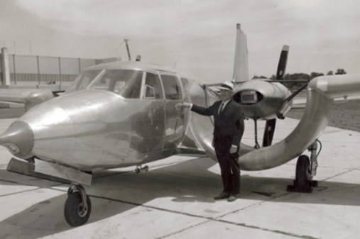
A design that led to rapid development for the present concept is the Custer Channel Wing, a largely forgotten attempt to create ultra-short takeoff and landing (USTOL) airplanes nearly a century ago, as is shown in Figure 1. Willard Custer came up with the idea of reversing the normal method of powered flight: instead of using the engines to push the aircraft through the air, he used the engine to suck the air across and through the wing, creating lift immediately when engine power was added.
Custer got the idea for his creation in the 1920s when he took refuge in a barn during a severe storm. He was stunned and fascinated to see the storm suck the roof off the barn and carry it away. Interested in aviation but not a pilot, Custer began a series of experimental aircraft designs incorporating large channels in the wings, which has been likened to a half-barrel shape. He was awarded 27 patents for his discoveries between 1929 and 1974; he built three different twin-engine aircraft in the 1940s and 1950s with his trademark curved ducts to channel air around the rotating propellers.
Unfortunately, in the case of Custer design, the channel area is reduced and the positive high lift effect is limited.
In our days, many people believe that unmanned aerial vehicles are opening the doors to move towards flying taxis. However, the greatest development happening at the moment comes in the form of cargo drones.
Recently, a Brazilian company Moya was financed by the Brazilian government with 2 million dollars to develop a tilting body drone as shown in Figure 2.
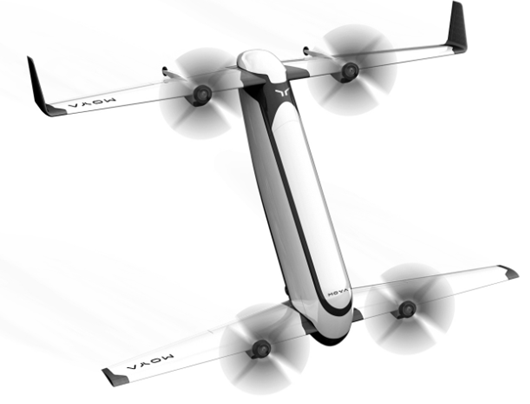
This concept has a number of issues:
-in forward flight, it exposes a maximum surface to the frontal airflow and this increases the drag, reducing the range;
-the propulsion system with four propellers is not redundant;
-no thrust augmentation effects and consequently has an increased energy consumption in take-off/landing;
-with this shape cannot transport containers;
-during take-off, it appears friction between the vehicle and the ground;
-unprotected rotors which increase the risk of contact with the environment or with the people around.
The channel propulsion CP – a radical improvement
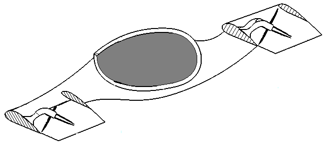
CP is a new propulsion principle of thrust augmentation and high lift with a double biplane wing system, increasing substantially the channel surface, as is shown in Figure 3.
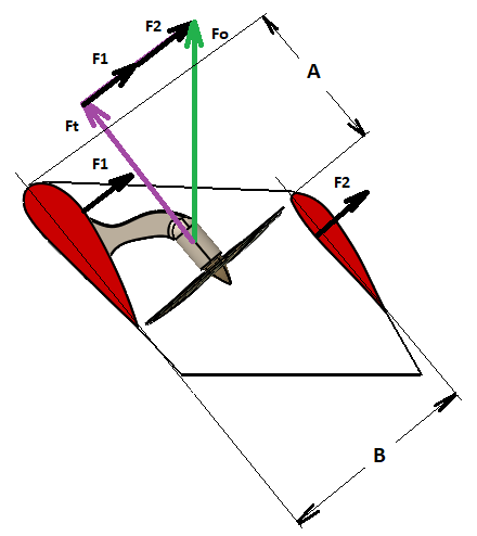
CP has a double biplane wing structure that uses a thrust augmenter configuration to increase the lift in both vertical and forward flights. In static conditions and at slow speeds, the lift capacity increases due to higher circulation around the wings, improving the aircraft’s thrust/weight ratio characteristic. Consequently, the weight is balanced by the sum of the thrust produced by the propeller and the lift produced by the wings. Because each front wing of each thrust unit is placed in the inlet region of the propeller it will develop a certain amount of lift due to the suction effect. On the lower surface, the pressure will be equal to the atmospheric pressure, while on the upper surface, the pressure will be slightly lower. As in the case of the front wing, because each rear wing of each thrust unit is placed in the outlet region of the propeller it will develop a certain amount of lift as well due to the increased pressure exercised on the lower surface of the rear wing.
Moreover, the propulsion system can be seen as a channel wing propulsion where in stands of a circular channel (already confirmed as being a high lift configuration) is used a rectangular channel having a substantially bigger dimension than Custer wings. In this case, the entire channel surface is airfoiled, thus it can generate lift when air flows over it. With the placement of a propulsion system within the channel, close to its trailing edge, air can be sucked over the channel surface. The reason for putting the propulsion system near the trailing edge is to use the maximum possible channel surface to generate lift. When the electric motors are running, and the aircraft is standing still or moving with a low forward speed, the air flowing through the channel is high with respect to the speed of the air below the channel surface. Thus, a high-pressure region below the channel and a low-pressure region over the channel are created. Consequently, a high amount of lift is generated that could not normally be produced by a conventional wing arrangement. Even at high speeds, the increased velocity of the airflow around the entire wing span generates an improved high lift.
Using this configuration, the propulsion system can have another important feature, respectively the propeller deactivation in cruising flight, without increasing the drag, but obtaining an improved efficiency.
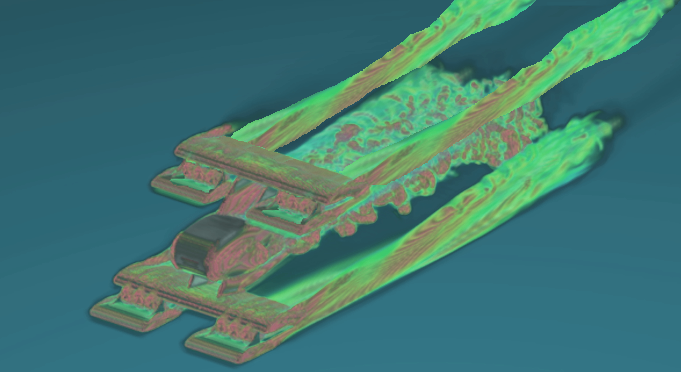
A CFD simulation was achieved for a preliminary configuration (Fig. 4). This showed a substantially improved flying efficiency even though this variant doesn’t use the entire wingspan as the last proposal.
A number of independent experiments were made to demonstrate the benefits of “over the wing propeller” by Delft University of Technology, from Holland as can be seen in Figure 5.
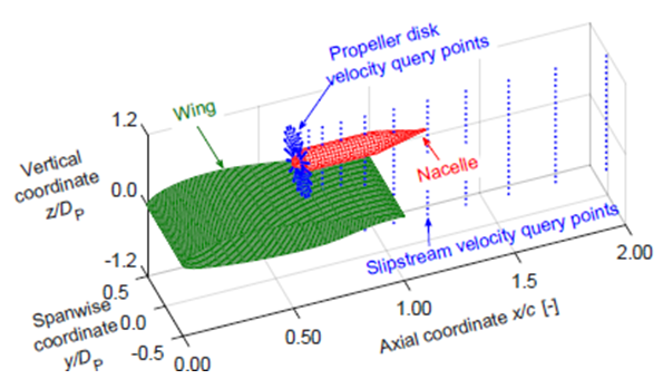
Conclusion: even in the case of an isolated propeller there are substantial advantages compared with the current technologies.
CP propulsion integrated into a cargo drone configuration
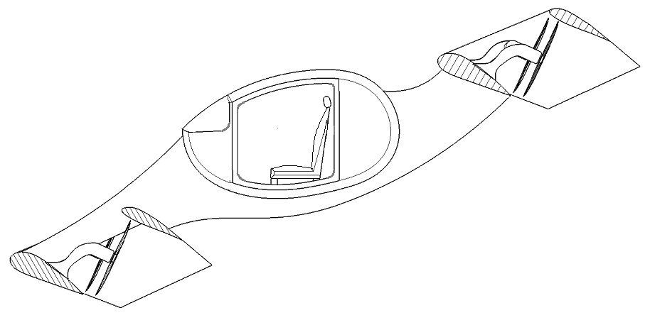
A cargo drone configuration was proposed. The fuselage has preferably an ovoid aerodynamic shape having substantially the same incidence angle as the wings (Figure 6).
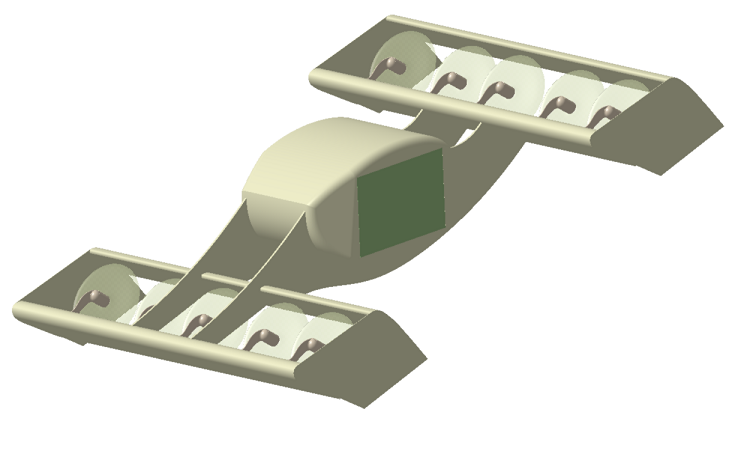
The fuselage is supported by two longitudinal beams. The drone uses two biplane thrust units merged by the two beams. In the middle area of the fuselage, the drone can transport at least one standard container.
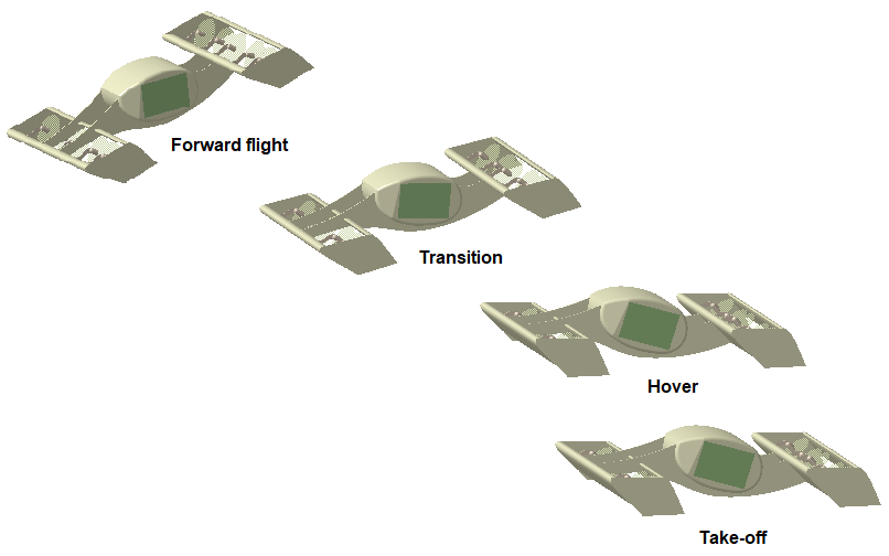
In operation, the drone tilts progressively the body until the forward flight position as is shown in Figure 7.
At cruising speed, the drone can deactivate 40% of the propellers, which greatly increases the flight efficiency as shown in Figure 8.
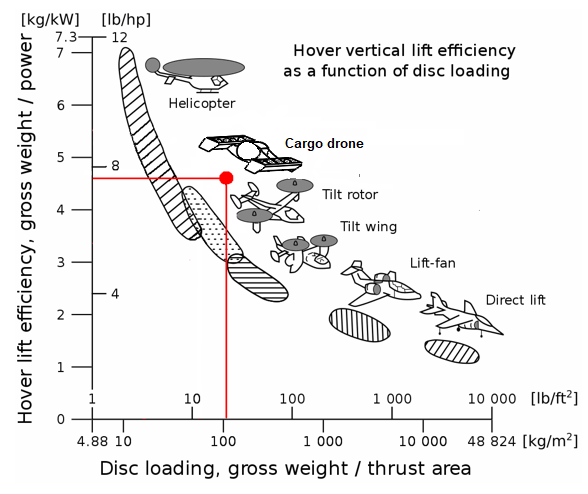
The traditional way of determining vertical flight and hovering efficiency is to consider the power loading of the vehicle. This is a simple ratio between the vehicle’s weight and the installed power. A more efficient vehicle requires a less powerful engine to hover at a given weight. Another method of measuring hover efficiency is disc loading, i.e., (Weight of vehicle) / (Area of thrust-producing structure). A VTOL aircraft with high power loading and low disc loading is the most efficient at hovering, as is the case for our cargo drone (Figure 9).
Other new VTOL configurations with CP
The cargo drone configuration is considered to be certified faster than a passenger vehicle, so will be produced first.
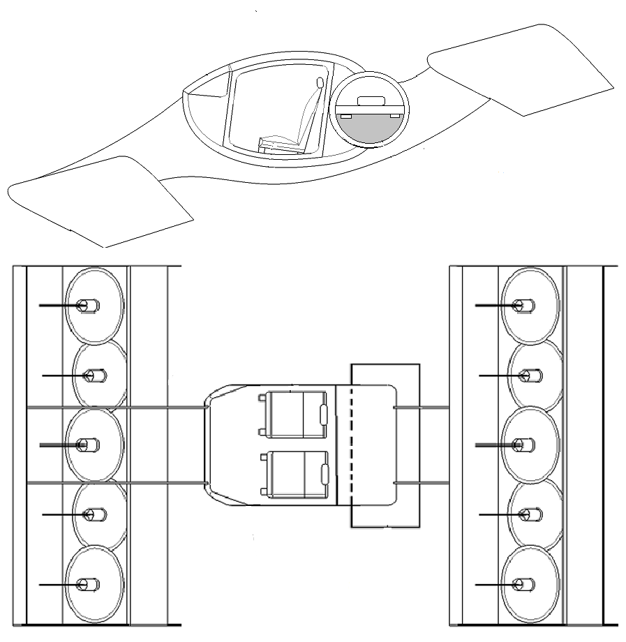
Later can be developed a passenger VTOL vehicle as is described in Figure 10.
Also, a cost-effective aerial ambulance will be of interest (Figure 11) for this new market.
CP advantages
Most current VTOL solutions are based on the design of the classic separation of the aircraft body and the propulsion system. With the synergic approach of the propulsion system and the configuration of the aircraft, new possibilities appear to improve the performance of the aircraft that are not otherwise possible. By integrating the propulsion system in a specific aircraft configuration very low specific traction levels can be achieved, thus paving the way for high efficiency associated with low noise levels. It is the case of Chanel Propulsion, several thrust-producing elements can be arranged so as to improve the aerodynamic characteristics of the aircraft. This generates high lift but can also produce beneficial cascading effects for example due to the feasibility of smaller lifting surfaces. In addition, the arrangement of several traction-producing elements may allow for new flight control options in terms of vectored and differential thrust, thus giving scope to decreasing or even eliminating control surface areas.
Summarizing, the CP and the associated aircraft configurations have the following advantages:
-The control of the vehicle is made by thrust differentiation, without pivoting propellers, wings, or flaps
-The aircraft construction is simple and cost-effective
-The drone can transport standard containers
-The take-off and landing are made vertically and not inclined
– The aircraft has an increased cruising speed and a reduced noise level.
-The embarked power of the energy source is diminished
-Same propulsion system is used for vertical flight as well as for forward flight
-It uses a thrust augmentation arrangement to increase the lift even at zero speed
-In forward flight, the lift is produced by the wings
-It is a highly efficient vehicle in both vertical and forward flight having an improved range
-The propellers are protected against contact with the environment or with the personnel on the ground
-It has a high redundancy level by using multiple thrust-producing elements
-It is a very compact vehicle that uses the entire wingspan to produce lift
-In forward flight can deactivate the propellers to increase even more the flight efficiency
-Because of the simplified construction, the maintenance costs are reduced
IP status
The CP principle is patented in the US with the number US11472545B2. Other several patent applications were registered in Europe.
Contact info:


